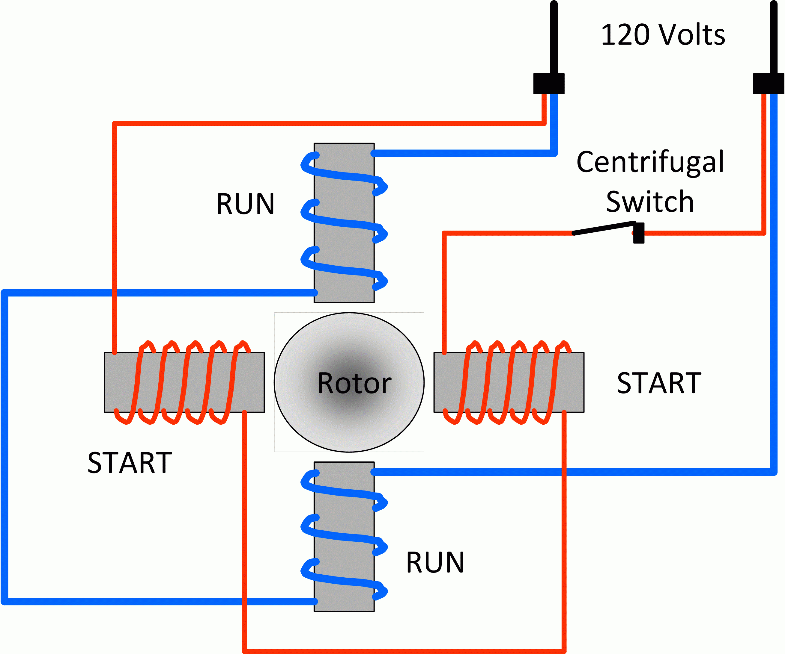
Single Phase Motor Run Capacitor Wiring Diagram
It is intended to help all the typical user in building a correct program. Each component ought to be placed and linked to different parts in particular manner.
Single Phase Motor Wiring Diagram With Capacitor Start
Run capacitor at the top, start capacitor at the bottom.

Single phase motor run capacitor wiring diagram. Injunction of two wires is usually. You will find out how to identify to main and auxilliary winding and change motor rotation.start capacitor, ru. Wiring diagram will come with numerous easy to follow wiring diagram directions.
Single phase motor wiring diagram with capacitor start capacitor run. However yellow is the start switch blue is the auxiliary winding and red is the main winding. How to wire single phase motor with capacitor.
How to wire a run capacitor to a motor blower & condenser hvac wiring the above illustration does not cover every single type of motor wiring available on the market. Each component should be placed and connected with other parts in particular manner. Capacitor start capacitor run induction motors are single phase induction motors that have a capacitor in the start winding and in the run winding as shown in figure 12 and 13 wiring diagram.
This type of motor is designed to provide strong starting torque and strong running for applications such as large water pumps. However, motor and capacitor diagram represents a vast majority of motors and capacitor wiring available to the general public. Learn how a capacitor start induction run motor is capable of producing twice as much torque of a split.
Begin capacitors briefly enhance motor beginning torque and permit a motor to be cycled on and off quickly. Single phase motor capacitor connection wiring diagram motors farm duty 10 hp 4p 215t 1ph 230 v 60 hz doerr lr22132 practical machinist largest w22 electric w01 ecn electrical forums specification guide weg 00518os1ccd184t odp compressor 2cv 4polos 110 220v three diagrams commercial air terminal identification yc. L1 and l2 are designated as the two connection points representing the two electricity flow path inherent with single phase circuits where a single phase supply voltage is fed to the motors internal circuit.
1 trick that we 2 to printing a similar wiring plan off twice. It is intended to help all the typical user in building a correct program. Single phase motor wiring diagram with.
This application note shows how to wire an optional switch to. Wiring diagram will come with numerous easy to follow wiring diagram directions. Single phase motor wiring diagram with capacitor baldor single phase motor wiring diagram with capacitor single phase fan motor wiring diagram with capacitor single phase motor connection diagram with capacitor every electrical arrangement is made up of various unique pieces.
It is intended to help all the typical user in building a correct program. This gives the following circuit diagram. These instructions will probably be easy to comprehend and implement.
If not, the structure will not. Hence by adding capacitor we get the two phase simultaneous from our single phase supply. Electric motor capacitor wiring diagram sample.
These instructions will probably be easy to comprehend and implement. All the information is there. However, it does not imply link between the cables.
With the help of the guide, you’ll be able to effortlessly do your own personal wiring tasks. Occasionally, the wires will cross. Push the wire terminal on the start capacitor s.
Single phase motor wiring diagram with capacitor wiring diagram is a simplified all right pictorial representation of an electrical circuitit shows the components of the circuit as simplified shapes and the aptitude and signal associates in the middle of the devices. Single phase motor wiring diagram with 2 capacitors. Psc motor typical wiring diagram for a psc motor definition and characteristics.
Hence the motor starts rotating. The reconnection must be carried out by qualified electrician. Capacitor start run motor wiring diagram website at tryit me in.
When you make use of your finger or perhaps the actual circuit with your eyes, it is easy to mistrace the circuit. Print the wiring diagram off plus use highlighters to trace the signal. You can often rely on wiring diagram being an important reference that can assist you to preserve time and cash.
Wiring diagram will come with numerous easy to follow wiring diagram directions. Click here to view a capacitor start motor circuit diagram for starting a single phase motor. According to earlier, the lines in a single phase motor wiring diagram with capacitor represents wires.
Single phase capacitor start motor wiring diagram from i.stack.imgur.com. The wiring colours to the motor suggest that this is a three phase motor, just to confuse me. Another split phase capacitor run type of electric motor utilizes a capacitor transformer unit and is of the split phase squirrel cage type with the main and auxiliary winding’s physically displaced in the stator.
Single phase motor wiring diagram with capacitor start roc grp org.
Baldor L1410t Capacitor Wiring Wiring Diagram
Motor Run Capacitor Wiring Diagram Wiring Diagram
Start Capacitor Run Motor Wiring Diagram Wiring Forums
Single Phase Capacitor Start Capacitor Run Motor Wiring
120 Volt Capacitor Start Motor Wiring
Single Phase Motor Wiring Diagram With Capacitor Start
Single Phase Motor Wiring Diagram With Capacitor Start
2 Capacitor induction motor Humming troubleshooting
Capacitor Start Motor Wiring Diagram Wiring Diagram
Starter Capacitor Wiring Diagram For Your Needs
☑ How To Wire A Capacitor Start Electric Motor
Hyderabad Institute of Electrical Engineers wiring
Collection Of Single Phase Hoist Wiring Diagram Sample
single phase capacitor startcapacitorrun motor wiring
Dayton Capacitor Start Motor Wiring Diagram Free Wiring
Ac Correct Wiring Of 1 Phase 220V Electrical Motor